Alle Kategorien
-
Integrierte schaltkreise (ICS)
Integrierte schaltkreise (ICS)
- Schnittstelle - Sensor, kapazitive Berührung(642)
- Spezialisierte ICS(12302)
- PMIC-Spannungsregler-besonderer Zweck(5644)
- PMIC-Spannungsregler-lineare Regler(793)
- PMIC-Spannungsregler-linear + Switching(1829)
- PMIC-Spannungsregler-linear(70981)
- PMIC-Spannungsregler-DC DC Switching Regulators(39569)
- PMIC-Regler-DC-DC-Switching-Controller(13507)
- PMIC-Spannungs-Referenz(9453)
- PMIC-v/f und f/v-Wandler(145)
- PMIC-Thermal Management(592)
- PMIC-Supervisor(47946)
- PMIC-RMS bis DC-Wandler(170)
- PMIC-Netzteil-Controller, Monitore(2104)
- PMIC-Power over Ethernet (PoE) Controller(1008)
- PMIC-Power Management-spezialisierte(7722)
- PMIC-Netzschalter, Treiber laden(7706)
- PMIC-PFC (Power Factor Correction)(1222)
- PMIC oder Steuerungen, ideale Dioden(705)
- PMIC-Motor-Treiber, Regler(4712)
- PMIC-Beleuchtung, Ballast-Regler(560)
- PMIC-LED-Treiber(7282)
- PMIC-Laser-Treiber(573)
- PMIC-Hot-Swap-Controller(2816)
- PMIC-Gate-Treiber(7083)
- PMIC-voll, Half-Bridge-Treiber(1342)
- PMIC-Energy Messung(654)
- PMIC-Display-Treiber(1435)
- PMIC-derzeitige Regulierung/Management(1481)
- PMIC-Batterie-Management(5553)
- PMIC-Ladegeräte(3831)
- PMIC-AC DC Konverter, Offline Schalter(4905)
- Memory-Controller(358)
- Memory-Konfigurations-Proms für FPGAs(639)
- Speicher-Akkus(13)
- Erinnerung(65694)
- Logic-universelle Bus-Funktionen(706)
- Logic-Übersetzer, Level-Shifter(2854)
- Logik-Specialty Logic(1870)
- Logik-Signal-Schalter, Multiplexer, Decoder(9420)
- Logic-Shift-Register(2665)
- Logic-Parity Generatoren und Checkers(335)
- Logic-multivibratoren(831)
- Logik-Latches(3658)
- Logik - Tore und Wechselrichter - Multifunktion, konfigurierbar(1687)
- Logik-Tore und Wechselrichter(16453)
- Logic-Flip Flops(7780)
- Logik-FIFOs Speicher(4240)
- Logik-Zähler, Trennlinien(3456)
- Logik-Vergleichsoperator(592)
- Logik-Puffer, Treiber, Receiver, Transceiver(17835)
- Linear-Video-Verarbeitung(2909)
- Linear-Vergleichsoperator(5084)
- Linear-analoge Multiplikatoren, Trennwände(263)
- Linear-Verstärker-Video Amps und Module(1905)
- Linear-Verstärker-Spezial-Zweck(1856)
- Linear - Verstärker - Instrumentierung, OP -Verstärker, Pufferverstärker(34236)
- Linear-Verstärker-Audio(4567)
- Interface-Voice Record und Playback(556)
- Schnittstelle - UARTs (Universal Asynchronous Receivers -Sender)(1236)
- Schnittstelle-Telecom(4467)
- Interface-spezialisierte(4833)
- Interface-Signal Terminatoren(333)
- Interface-Signal-Puffer, Repeater, Splitter(1449)
- Interface-Serializer, Deserializer(1480)
- Schnittstellen-Sensor und Detektor-Interfaces(1524)
- Interface-Module(169)
- Interface-Modems-ICS und Module(407)
- Interface-e/a-Expander(1136)
- Interface-Filter-aktiv(1226)
- Interface-Encoder, Decoder, Konverter(714)
- Interface-Treiber, Receiver, Transceiver(20755)
- Interface-Direct Digital Synthesis (DDS)(117)
- Interface-Controller(3628)
- Interface-Codecs(1676)
- Schnittstelle - Analoge Switches, Multiplexer, Demultiplexer(12567)
- Schnittstelle-analoge Schalter-spezieller Zweck(2533)
- Embedded-System on Chip (SoC)(4496)
- Embedded-PLDs (programmierbare Logik-Vorrichtung)(971)
- Embedded-Mikroprozessoren(10083)
- Embedded-Mikrocontroller-anwendungsspezifische(2275)
- Embedded-Mikrocontroller(99285)
- Eingebettet - Mikrocontroller, Mikroprozessor, FPGA -Module(1527)
- Eingebettet - FPGAs (Feldprogrammiergate -Array) mit Mikrocontrollern(81)
- Embedded-FPGAs (Field Programmable Gate Array)(27748)
- Embedded-DSP (Digital Signal Processors)(4081)
- Eingebettet - CPLDs (komplexe programmierbare Logikgeräte)(5187)
- Datenerfassung-Touch Screen Controller(1210)
- Datenerfassung-Digital to Analog Converter (DAC)(14419)
- Datenerfassung-digitale Potentiometer(6250)
- Datenerfassung-analog zu Digital Converters (ADC)(17776)
- Datenerfassung-analoges Frontend (AFE)(787)
- Datenerfassung-MDE/DACs-spezieller Zweck(3043)
- Clock/Timing-Uhren in Echtzeit(2446)
- Uhr/Timing - programmierbare Timer und Oszillatoren(23469)
- Clock/Timing-IC-Akkus(4)
- Takt/Timing-Delay Lines(1049)
- Uhr/Timing - Uhrengeneratoren, PLLS, Frequenzsynthesizer(32775)
- Clock/Timing-Clock Puffer, Treiber(4568)
- Clock/Timing-anwendungsspezifische(8652)
- Audio Spezial-Zweck(1564)
Relevanter Hersteller


-
Diskrete Halbleiter-Produkte
Diskrete Halbleiter-Produkte
- Aktuelle Regulierung - Dioden, Transistoren(1090)
- Transistoren-besonderer Zweck(226)
- Transistoren-programmierbare Unijunction(48)
- Transistoren-jfets(1558)
- Transistoren-IGBTs-Einzel(4799)
- Transistoren-IGBTs-Module(63420)
- Transistoren-IGBTs-Arrays(26)
- Transistoren-FETs, MOSFETs-Einzel(48330)
- Transistoren-FETs, MOSFETs-RF(4903)
- Transistoren-FETs, MOSFETs-Arrays(6641)
- Transistoren-Bipolar (BJT)-einzeln, Pre-biased(4539)
- Transistoren-Bipolar (BJT)-Einzel(25800)
- Transistoren-Bipolar (BJT)-RF(2087)
- Transistoren-bipolare (BJT)-Arrays, Pre-biased(2115)
- Transistoren-bipolare (BJT)-Arrays(2310)
- Thyristor-triacs(4044)
- Thyristoren-SCRs-Module(3967)
- Thyristoren-SCRs(5436)
- Thyristoren-diacs, sidacs(319)
- Power Driver Module(1627)
- Dioden-zenerdioden-Einzel(87483)
- Dioden-zenerdioden-Arrays(2619)
- Dioden - variable Kapazität (Varik, Varaktoren)(1200)
- Dioden-RF(2753)
- Dioden-Gleichrichter-Einzel(67528)
- Dioden-Gleichrichter-Arrays(20581)
- Dioden-Brücke-Gleichrichter(11700)
Relevanter Hersteller


-
RF/if und RFID
RF/if und RFID
- SIM -Karten für Abonnenten -Identifikationsmodul (SIM)(77)
- RF -Zirkulatoren und Isolatoren(1742)
- RFID, RF-Zugang, Monitoring-ICS(1550)
- RFID Transponder, Tags(747)
- RFID Lesegeräte(464)
- RFID -Bewertungs- und Entwicklungskits, Boards(30)
- RFID Antennen(329)
- RFI und EMI - Abschirm- und Absorbungsmaterialien(6444)
- HF und EMI-Kontakte, Fingerstock und Dichtungen(7497)
- RF Transmitter(668)
- RF Transceiver Module(6900)
- RF-Transceiver ICS(4169)
- HF-Schalter(9276)
- RF Shields(16401)
- HF-Receiver(1998)
- HF -Empfänger, Sender und Transceiver -Einheiten(2763)
- RF Power Divider/Splitter(1223)
- RF Power Controller ICs(86)
- HF-Modulatoren(710)
- HF-Mixer(2800)
- RF misc ICS und Module(3276)
- HF-Front-End (LNA + PA)(419)
- RF -Bewertungs- und Entwicklungskits, Boards(747)
- HF-gerichtete Kupplung(2718)
- RF Diplexer(1464)
- RF-Detektoren(412)
- RF-Demodulatoren(249)
- HF-Antennen(12319)
- HF-Verstärker(19651)
- Balun(1496)
- Dämpfungsglieder(4852)
Relevanter Hersteller


-
Optoelektronik
Optoelektronik
- Optomechanisch(480)
- Leuchten(125)
- Laserdioden, Lasermodule - Laserlieferung, Laserfasern(345)
- Hene Lasersysteme(31)
- Hene Laserköpfe(27)
- Hintergrundbeleuchtung anzeigen(93)
- Xenon-Beleuchtung(387)
- Touchscreen-Overlays(453)
- Panel Indicators, Pilot Lights(75729)
- Optik-Remote-Phosphor-Lichtquelle(269)
- Optik-Reflektoren(665)
- Optik-leichte Rohre(5384)
- Optik-Objektive(4951)
- LEDs-Spacer, Unentschieden(2718)
- LEDs-Lamp-Ersetzungen(29718)
- LEDs - Leiterplattenindikatoren, Arrays, Lichtstäbe, Balkendiagramme(9083)
- LED-thermische Produkte(667)
- LED-Beleuchtung(64)
- LED-Beleuchtung-weiß(37580)
- LED-Beleuchtung-Farbe(4728)
- LED-Beleuchtung-Maiskolben, Motoren, Module(28735)
- LED-Anzeige-diskret(27601)
- Laserdioden, Module(1553)
- Lampen-Glühlampen, Neons(311004)
- Lampen-Kälte-Fluoreszenz (KKL) & UV(164)
- Wechselrichter(7728)
- Infrarot, UV, sichtbare Strahler(3871)
- Fiber Optics-Transmitter-Antrieb integriert(4085)
- Fiber Optics-Transmitter-diskrete(350)
- Fiber Optics-Transceiver Module(18758)
- Fiberoptik-Switches, Multiplexer, Demultiplexer(1387)
- Fiberoptik-Receiver(695)
- Fiberoptik-Dämpfung(654)
- Elektrolumineszenz(102)
- Display, Monitor-Interface Controller(98)
- Display-Module-Vakuum-Leuchtstofflampen (VFD)(249)
- Module anzeigen-LED Dot Matrix und Cluster(865)
- Display-Module-LED-Zeichen und numerische(5421)
- Display-Module-LCD, OLED, Graphic(4654)
- Display-Module-LCD, OLED-Zeichen und numerische(2202)
- Display-Blenden, Objektive(88)
- Adresse, Spezialität(458)
Relevanter Hersteller


-
Sensoren, Wandler
Sensoren, Wandler
- Ultraschallempfänger, Sender - Industrial(115)
- Temperatursensoren - Thermostate - Mechanisch - Industrielles(3103)
- Temperatursensoren - Analog und digitaler Ausgang - Industrial(209)
- Näherungssensoren - Industrial(13611)
- Drucksensoren, Wandler - Industrie(26503)
- Optische Sensoren - Photonik - Zähler, Detektoren, SPCM (Einzelphotonzählmodul)(751)
- Optische Sensoren - Kameramodule(875)
- Magnetsensoren - Position, Nähe, Geschwindigkeit (Module) - Industrie(554)
- Kraftsensoren - Industrial(346)
- Flusssensoren - Industrielles(151)
- Float, Level Sensoren - Industrial(310)
- Encoder - Industrial(4980)
- Farbsensoren - Industrial(50)
- Berührungssensoren(100)
- Ultraschall-Receiver, Transmitter(2421)
- Temperatursensoren-Thermostat-Solid State(1096)
- Temperatursensoren-Thermostate-mechanisch(3397)
- Temperatursensoren - Thermoelemente, Temperatursonden(1921)
- Temperatursensoren - RTD (Widerstandstemperaturdetektor)(1525)
- Temperatursensoren-PTC-Thermistoren(2273)
- Temperatursensoren-ntc-thermistoren(13259)
- Temperatursensoren-Analog und Digital Output(3928)
- DMS(1399)
- Spezialisierte Sensoren(1861)
- Solarzellen(503)
- Schock-Sensoren(84)
- Sensor-Interface-Junction-Blöcke(2519)
- Sensor-Kabel-Baugruppen(22011)
- Proximity/Belegung Sensoren-fertige Einheiten(725)
- Näherungsschalter(2860)
- Drucksensoren, Wandler(11317)
- Positionssensoren - Winkel, lineare Positionsmessung(6022)
- Optische Sensoren-reflektierende-Logik-Ausgang(194)
- Optische Sensoren - reflektierend - analoge Ausgang(432)
- Optische Sensoren-Phototransistoren(1027)
- Optische Sensoren - Photointerrupter - Schlitztyp - Transistorausgang(1427)
- Optische Sensoren - Photointerrupter - Schlitztyp - Logikausgabe(1215)
- Optische Sensoren-Lichtschranke, Industrial(16763)
- Optische Sensoren-Photodioden(1543)
- Optische Sensoren-Foto-Detektoren-Remote Receiver(2605)
- Optische Sensoren-Foto-Detektoren-Logik-Ausgang(146)
- Optische Sensoren-Foto-Detektoren-CDs-Zellen(74)
- Optische Sensoren-Distanz-Messung(377)
- Optische Sensoren-Ambient Light, IR, UV Sensoren(1305)
- Multifunktions(558)
- Motion Sensors-Vibration(337)
- Motion Sensors-Tilt Schalter(67)
- Bewegungsmelder-optisch(719)
- Motion Sensors-Neigungssensoren(175)
- Motion Sensors-Imus (Trägheit-Maßeinheiten)(416)
- Motion Sensors-Kreisel(214)
- Motion Sensors-Beschleunigungsmesser(1911)
- Magnete-Sensor abgestimmt(119)
- Magnete-Multi Purpose(1965)
- Magnetische Sensoren-Schalter (Solid State)(3700)
- Magnetsensoren - Position, Nähe, Geschwindigkeit (Module)(5199)
- Magnetische Sensoren-linear, Kompass (ICS)(1247)
- Magnetsensoren - Kompass, Magnetfeld (Module)(35)
- LVDT -Wandler (linearer variabler Differentialtransformator)(204)
- IrDA Transceiver-Module(196)
- Bildsensor, Kamera(2235)
- Feuchtigkeit-Sensoren(1425)
- Gas-Sensoren(1217)
- Force Sensoren(188)
- Durchfluss-Sensoren(550)
- Float, Level Sensoren(1343)
- Encoder(6357)
- Staub-Sensoren(43)
- Aktuelle Wandler(3455)
- Color Sensoren(85)
- Verstärker(1905)
Relevanter Hersteller


-
Anschlüsse, Verbindungen
Anschlüsse, Verbindungen
- USB, DVI, HDMI -Stecker(446)
- Festkörperbeleuchtungsstecker(555)
- Steckdosen für ICs, Transistoren(953)
- Steckbare Steckverbinder(1221)
- Photovoltaik (Solarpanel) Anschlüsse(136)
- Glasfaseranschlüsse(370)
- FFC, FPC (flache flexible) Anschlüsse(761)
- D-Sub, D-förmige Stecker(2887)
- Koaxialverbinder (RF)(2389)
- Rundanschlüsse(14162)
- Stromanbeter Blade Type(273)
- Stecker und Behälter(2597)
- USB, DVI, HDMI Stecker-Adapter(572)
- USB, DVI, HDMI -Stecker(4298)
- Klemmen-Wire to Board Steckverbinder(217)
- Klemmen-Draht-Steckverbinder(4322)
- Klemmen-Draht-Pin Stecker(328)
- Terminals-Revolver Steckverbinder(1273)
- Terminals-spezialisierte Steckverbinder(2042)
- Klemmen-Spaten Verbinder(3902)
- Klemmen-Löten/Stecker(345)
- Klemmen-Verschraubungen(745)
- Klemmen-Ring Steckverbinder(12596)
- Klemmen-rechteckige Steckverbinder(4747)
- Terminals - Schnellverbindungen, schnelle Trennungsanschlüsse(8514)
- Klemmen-PC PIN, Single Post Connectors(3776)
- Klemmen-PC-Pin-Buchsen, Sockel-Steckverbinder(5883)
- Klemmen-magnetische Draht-Steckverbinder(1653)
- Klemmen-Messer Steckverbinder(112)
- Klemmen-Gehäuse, Stiefel(2850)
- Klemmen-Folie Steckverbinder(108)
- Klemmen-Barrel, Bullet-Steckverbinder(1107)
- Klemmen-Adapter(137)
- Terminal-Streifen und Revolver-Boards(1159)
- Terminal Junction Systeme(2533)
- Anschlussblöcke-Draht an Bord(43615)
- Terminal Blocks-spezialisierte(3722)
- Terminal Blocks-Power Distribution(847)
- Anschlussblöcke-Panel Mount(1359)
- Terminal Blocks-Interface Module(1819)
- Anschlussblöcke-Kopfzeilen, Stecker und Buchsen(119920)
- Anschlussblöcke-DIN-Schiene, Kanal(9373)
- Anschlussblöcke-Kontakte(65)
- Anschlussblöcke-Barrier Blocks(47517)
- Anschlussblöcke-Adapter(1059)
- Solid State Lighting Verbinder-Kontakte(271)
- Festkörperbeleuchtungsstecker(1344)
- Buchsen für ICS, Transistoren-Adapter(275)
- Steckdosen für ICs, Transistoren(22148)
- Shunts, Jumper(907)
- Rechteckige Verbinder-Feder geladen(7721)
- Rechteckige Steckverbinder-Gehäuse(43023)
- Rechteckige Verbinder-Kopfzeilen, Spezial-PIN(6129)
- Rechteckige Anschlüsse - Header, Gefäße, weibliche Sockel(229601)
- Rechteckige Verbinder-Kopfzeilen, männliche Pins(543338)
- Rechteckige Anschlüsse - kostenloses Hängen, Panelhalterung(30142)
- Rechteckige Verbinder-Kontakte(10681)
- Rechteckige Anschlüsse - Board in, Direktdraht zum Board(2432)
- Rechteckige Verbinder-Adapter(475)
- Rechteckig - Brett zu Board -Steckern - Header, Behälter, weibliche Sockel(9)
- Rechteckig - Brett zu Board -Steckern - Header, männliche Stifte(2)
- Rechteckige Anschlüsse - Board -Abstandshalter, Stacker (Board zu Board)(238901)
- Rechteckige Anschlüsse - Arrays, Kantentyp, Mezzanin (Board zu Board)(37853)
- Stromanschluss-Eingänge, Steckdosen, Module(10310)
- Steckbare Steckverbinder(6049)
- Photovoltaik- (Solarpanel) Anschlüsse - Kontakte(77)
- Photovoltaik (Solarpanel) Anschlüsse(504)
- Modulare Steckverbinder-Verdrahtung Blöcke(99)
- Modulare Steckverbinder-Stecker(1674)
- Modulare Steckverbinder-Stecker Gehäuse(181)
- Modulare Steckverbinder-Buchsen mit magnetischen(10152)
- Modulare Steckverbinder-Buchsen(23416)
- Modulare Steckverbinder-Adapter(855)
- Memory Connectors-PC Cards-Adapter(21)
- Memory Connectors-PC Card Sockets(3299)
- Memory Connectors-Inline Modul Sockets(3390)
- LGH Steckverbinder(764)
- Keystone-Einsätze(2758)
- Keystone-Frontplatte, Frames(1926)
- Heavy Duty Steckverbinder-Einsätze, Module(4190)
- Schwerlastanschlüsse - Gehäuse, Kapuzen, Basen(17226)
- Heavy Duty Steckverbinder-Frames(523)
- Heavy Duty Steckverbinder-Kontakte(1832)
- Heavy Duty Steckverbinder-Baugruppen(671)
- LWL-Steckverbinder-Gehäuse(919)
- Glasfaser-Steckverbinder - Adapter(4455)
- LWL-Steckverbinder(3001)
- FFC, FPC (flache flexible) Steckverbinder - Gehäuse(652)
- FFC, FPC (flache flexible) Anschlüsse - Kontakte(202)
- FFC, FPC (flache flexible) Anschlüsse(18691)
- D-Sub, d-förmige Steckverbinder-Terminatoren(47)
- D-Sub, d-förmige Steckverbinder-Gehäuse(12238)
- D-Sub, d-förmige Steckverbinder-Kontakte(2714)
- D-Sub, D-förmige Steckverbinder-Rückenschalen, Kapuzen(5995)
- D-Sub, d-förmige Steckverbinder-Adapter(1304)
- D-Sub Steckverbinder(141346)
- D-förmige Steckverbinder-Centronics(8770)
- Kontakte, Frühling geladen und Druck(630)
- Kontakte-Multi Purpose(6196)
- Kontakte-"Leadframe"(122)
- Koaxial-Steckverbinder (RF)-Terminatoren(1231)
- Koaxial-Steckverbinder (RF)-Kontakte(480)
- Koaxial-Steckverbinder (RF)-Adapter(6386)
- Koaxialverbinder (RF)(25734)
- Rundsteckverbinder-Gehäuse(441226)
- Rundsteckverbinder-Kontakte(4737)
- Rundsteckverbinder-backschalen und Kabel-Klemmen(53692)
- Rundsteckverbinder-Adapter(8839)
- Rundanschlüsse(1196254)
- Card Edge Steckverbinder-Gehäuse(469)
- Karte Edge Verbinder-edgeboard Verbinder(672683)
- Card Edge Verbinder-Kontakte(325)
- Card Edge Verbinder-Adapter(73)
- Blade Type Power Steckverbinder-Gehäuse(837)
- Blade Type Power Connectors-Kontakte(393)
- Stromanbeter Blade Type(4163)
- Zwischen Serien-Adapter(649)
- Barrel-Stromanschluss(935)
- Barrel-Audio-Anschlüsse(2432)
- Barrel-Audio Adapter(92)
- Banana und Tip Steckverbinder-Buchsen, Stecker(1644)
- Banana and Tip Connectors-Binding Posts(239)
- Banana und Tip Steckverbinder-Adapter(75)
- Backplane Steckverbinder-spezialisiert(45586)
- Backplane Steckverbinder-Gehäuse(6863)
- Backplane Steckverbinder-Hard metrisch, Standard(6297)
- Backplane Steckverbinder-DIN 41612(9408)
- Backplane Steckverbinder-Kontakte(3583)
- Backplane Connectors-ARINC Einsätze(2357)
- Backplane Steckverbinder-ARINC(3789)
Relevanter Hersteller


-
Widerstände
-
Kondensatoren
Kondensatoren
- Aluminium-Elektrolytkondensatoren(16817)
- Trimmer, Variable Kondensatoren(3151)
- Dünne Folien-Kondensatoren(3473)
- Tantal-Kondensatoren(136103)
- Tantal-Polymer-Kondensatoren(9778)
- Silizium-Kondensatoren(320)
- Niob Oxide Kondensatoren(330)
- Mica und PTFE Kondensatoren(9101)
- Folien-Kondensatoren(150406)
- Elektrische Doppelschichtkondensatoren (EDLC), Superkondensatoren(2782)
- Keramische Kondensatoren(833829)
- Kondensatoren-Netzwerke, Arrays(2383)
- Aluminium-Elektrolytkondensatoren(125325)
- Aluminium-Polymer-Kondensatoren(7544)
Relevanter Hersteller


-
Transformatoren
Transformatoren
Relevanter Hersteller


-
Isolatoren
-
Kristalle, Oszillatoren, Resonatoren
Kristalle, Oszillatoren, Resonatoren
Relevanter Hersteller


-
Switches
Switches
- Verriegelungsschalter(2893)
- Emergency-Stop-Schalter (E-Stop)(1160)
- Kabelzugschalter(571)
- Toggle-Schalter(33608)
- Rändelrads Schalter(742)
- Schalter(14263)
- Snap-Aktion, Endschalter begrenzen(28077)
- Slide-Schalter(5166)
- Selector-Schalter(9720)
- Rotary Switches(13850)
- Rocker Schalter(53790)
- Drucktaste-Schalter-Hall-Effekt(127)
- Drucktaste Schalter(190826)
- Programmierbare Display-Switches(39)
- Navigations-Schalter, Joystick(1882)
- Magnetische, Reed-Schalter(1399)
- Keypad-Schalter(637)
- Keylock Schalter(3684)
- DIP Schalter(7747)
- Konfigurierbare Switch-Komponenten-Objektiv(1435)
- Konfigurierbare Schalter-Komponenten-Lichtquelle(1236)
- Konfigurierbare Switch-Komponenten-Contact Block(1401)
- Konfigurierbare Switch-Komponenten-Body(16077)
- Disconnect-Switch-Komponenten(2567)
Relevanter Hersteller


-
Relais
Relais
- Sicherheitsrelais(1310)
- Reedrelais(1735)
- Hochfrequenz (RF) -Relais(1190)
- Schütze (Festkörper)(686)
- Schütze (elektromechanisch)(11952)
- Kfz-Relais(1881)
- Solid State Relais(10652)
- Signal-Relais, bis zu 2 Ampere(9149)
- Relay-Sockets(2075)
- Power Relays, über 2 Ampere(31604)
- E / A-Relaismodule(712)
- I/o-Relay-Module-Input(2)
- I/o-Relay-Modul-Racks(247)
Relevanter Hersteller


Sprache auswählen
Aktuelle Sprache
Deutsch
- English
- Deutsch
- Italia
- Français
- 日本語
- 한국의
- русский
- Svenska
- Nederland
- español
- Português
- polski
- Suomi
- Gaeilge
- Slovenská
- Slovenija
- Čeština
- Melayu
- Magyarország
- Hrvatska
- Dansk
- românesc
- Indonesia
- Ελλάδα
- Български език
- Afrikaans
- IsiXhosa
- isiZulu
- lietuvių
- Maori
- Kongeriket
- Монголулс
- O'zbek
- Tiếng Việt
- हिंदी
- اردو
- Kurdî
- Català
- Bosna
- Euskera
- العربية
- فارسی
- Corsa
- Chicheŵa
- עִבְרִית
- Latviešu
- Hausa
- Беларусь
- አማርኛ
- Republika e Shqipërisë
- Eesti Vabariik
- íslenska
- မြန်မာ
- Македонски
- Lëtzebuergesch
- საქართველო
- Cambodia
- Pilipino
- Azərbaycan
- ພາສາລາວ
- বাংলা ভাষার
- پښتو
- malaɡasʲ
- Кыргыз тили
- Ayiti
- Қазақша
- Samoa
- සිංහල
- ภาษาไทย
- Україна
- Kiswahili
- Cрпски
- Galego
- नेपाली
- Sesotho
- Тоҷикӣ
- Türk dili
- ગુજરાતી
- ಕನ್ನಡkannaḍa
- मराठी
Leitfaden zum 2N2646 UJT und seinen Anwendungen
Zeit: 2025/12/23
Durchsuchen: 492
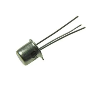
Der 2N2646

2N2646
Solid State Inc.
UNI JUNCT TRANS TO18
Out Stock
Unijunction Transistor (UJT) ist ein klassisches Halbleiterbauelement.In diesem Artikel werden die Merkmale, Spezifikationen, Anwendungen und die praktische Verwendung des Unijunction-Transistors 2N2646 in elektronischen Schaltkreisen erläutert.
Katalog
2N2646 Transistor Basic
Die 2N2646
2N2646
Solid State Inc.
UNI JUNCT TRANS TO18
Out Stock
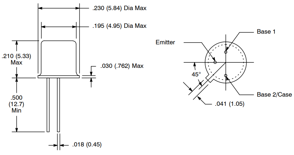
Der Unijunction Transistor (UJT) ist ein Siliziumschaltgerät, das hauptsächlich für Timing- und Triggeranwendungen entwickelt wurde.Im Gegensatz zu herkömmlichen Bipolartransistoren verfügt er über einen einzigen PN-Übergang und drei Anschlüsse: Emitter, Basis 1 und Basis 2. Er ist vor allem für seine negative Widerstandscharakteristik bekannt, die ein schnelles Schalten ermöglicht, sobald eine bestimmte Emitterspannung erreicht ist.
Wenn Sie Interesse am Kauf des 2N2646 haben, kontaktieren Sie uns bitte bezüglich Preis und Verfügbarkeit.
2N2646 Transistor-CAD-Modelle
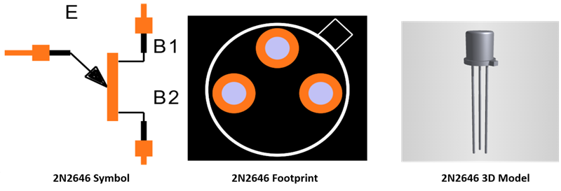
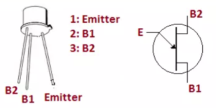
Details zur Pinbelegung des Transistors 2N2646
|
Pin
Nein. |
Pin
Name |
Beschreibung |
|
1 |
Emitter (E) |
Löst den UJT aus
wenn die Emitterspannung das intrinsische Abstandsverhältnis erreicht |
|
2 |
Basis 1 (B1) |
Untere Basis
Anschluss, der in Stromkreisen normalerweise mit der Erde verbunden ist |
|
3 |
Basis 2 (B2) |
Oberer Sockel
Klemme, üblicherweise mit der Versorgungsspannung verbunden |
Alternativen und gleichwertiges Modell
• 2N2647

2N2647
Solid State Inc.
TO 18 UNIJUNCTION TRANSISTOR
Out Stock
• 2N4870

2N4870
Solid State Inc.
TO 92 UNIJUNCTION TRANSISTOR
Out Stock
• 2N4871
2N4871
Solid State Inc.
TO 92 UNIJUNCTION TRANSISTOR
Out Stock
• 2N1671

2N1671
Solid State Inc.
TO 5 UNIJUNCTION TRANSISTOR
In Stock: 5244 pcs
• 2N1670
• 2N6027

2N6027
Central Semiconductor
PROGRAMMABLE UJT 40V TO226-3
In Stock: 73661 pcs
• 2N6028
2N6028
Solid State Inc.
PUT TO92
Out Stock
• NTE6401

NTE6401
NTE Electronics, Inc
T-UNIJUNCTION SI
In Stock: 121 pcs
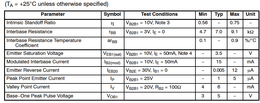
2N2646 Transistorspezifikationen
|
Spezifikation |
Bewertung |
|
Gerätetyp |
Silizium
Unijunction-Transistor (UJT) |
|
Maximal
Interbase-Spannung |
35 V |
|
Maximaler Emitter
Sperrspannung |
30 V |
|
Spitzenemitter
Aktuell |
2 A (Impuls) |
|
RMS-Emitter
Aktuell |
50mA |
|
Interbase
Widerstand |
4 kΩ – 9 kΩ |
|
Intrinsisch
Abstandsverhältnis |
0,5 – 0,8 |
|
Macht
Zerstreuung |
300 mW |
|
Betrieb
Temperaturbereich |
−65 °C bis +125
°C |
|
Lagerung
Temperatur |
−65 °C bis +150
°C |
|
Paket |
TO-39 (Metall
Kann) |
|
Anzahl
Terminals |
3 (E, B1, B2) |
Elektrische Eigenschaften
2N2646 Transistorfunktionen
Negative Widerstandscharakteristik
Der 2N2646
2N2646
Solid State Inc.
UNI JUNCT TRANS TO18
Out Stock
weist einen negativen Widerstandsbereich auf, sobald die Emitterspannung ihre Auslöseschwelle erreicht.Dieses einzigartige Verhalten ermöglicht es dem Gerät, schnell von einem nichtleitenden in einen leitenden Zustand zu wechseln, was es ideal für Impulserzeugungs- und Zeitschaltkreise macht.
Einfache Auslöseoperation
Dieser UJT erfordert zum Einschalten nur einen geringen Anstieg der Emitterspannung, sodass keine komplexe Vorspannung erforderlich ist.Sein vorhersehbarer Auslösepunkt erleichtert den Entwurf stabiler und wiederholbarer Oszillator- und Steuerschaltungen.
Zuverlässige Timing-Leistung
Das intrinsische Abstandsverhältnis des 2N2646 ermöglicht ein konsistentes Timing bei Verwendung mit einfachen Widerstands-Kondensator-Netzwerken (RC).Dadurch eignet es sich gut für Relaxationsoszillatoren und Verzögerungsschaltungen mit minimaler Komponentenanzahl.
Großer Betriebstemperaturbereich
Der 2N2646 ist für den zuverlässigen Betrieb über einen breiten Temperaturbereich ausgelegt und arbeitet sowohl in Industrie- als auch Bildungsumgebungen zuverlässig, selbst unter wechselnden thermischen Bedingungen.
Hohe Impulsstromfähigkeit
Obwohl es mit einem niedrigen Durchschnittsstrom arbeitet, kann das Gerät kurzzeitig hohe Spitzenemitterströme bewältigen.Diese Funktion ist besonders nützlich zum Auslösen von SCRs und TRIACs in Leistungssteuerungsanwendungen.
Geringer Stromverbrauch
Der 2N2646 verbraucht im Normalbetrieb sehr wenig Strom.Diese Effizienz trägt dazu bei, die Wärmeerzeugung zu reduzieren und die Zuverlässigkeit bei Schaltanwendungen im Dauerbetrieb und bei niedrigen Frequenzen zu verbessern.
2N2646 Arbeiten im Schaltkreis
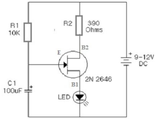
2N2646 als Relaxationsoszillator (LED-Blinkerschaltung)
In dieser Schaltung arbeitet der 2N2646
2N2646
Solid State Inc.
UNI JUNCT TRANS TO18
Out Stock
als Relaxationsoszillator, der periodische Impulse erzeugt.Der Kondensator lädt sich langsam über den Widerstand auf, bis die Emitterspannung die intrinsische Abstandsschwelle des UJT erreicht.An diesem Punkt schaltet sich der 2N2646 plötzlich ein und entlädt den Kondensator schnell über Basis 1. Diese schnelle Entladung erzeugt einen Stromimpuls, der die LED zum Leuchten bringt.Sobald die Kondensatorspannung abfällt, schaltet sich der UJT wieder aus und der Zyklus wiederholt sich, was zu einer blinkenden LED führt.Die Blinkfrequenz hängt hauptsächlich von den Widerstands- und Kondensatorwerten ab.
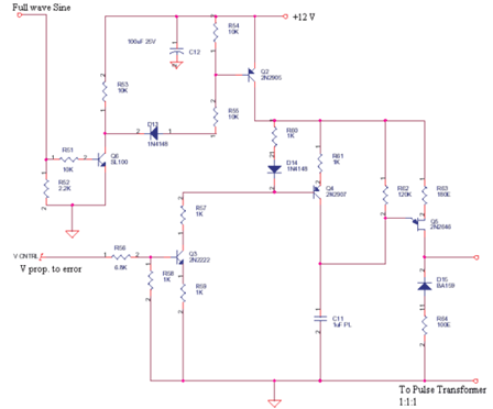
2N2646 als Auslösegerät (Impulssteuerkreis)
Hier wird der 2N2646 verwendet, um scharfe Triggerimpulse für andere Komponenten wie SCRs oder Impulstransformatoren zu erzeugen.Das RC-Netzwerk legt das Timing fest, während der UJT einen schnellen und sauberen Übergang bei Erreichen des Schwellenwerts gewährleistet.Wenn der Emitter zündet, erzeugt die plötzliche Stromänderung an Basis 1 einen schmalen Impuls.Damit eignet sich der 2N2646 ideal für präzise und wiederholbare Triggerungen in der Steuerungs- und Leistungselektronik.
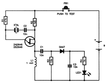
2N2646 als Impuls- und Zeitgenerator
In dieser Anwendung wird der 2N2646 mit Induktivitäten, Dioden und Kondensatoren kombiniert, um Impulse und Verzögerungen zu formen.Der UJT steuert, wann die in den Zeitsteuerungskomponenten gespeicherte Energie freigesetzt wird, und erzeugt so kontrollierte Ausgangsimpulse.Seine negative Widerstandscharakteristik ermöglicht einen stabilen Betrieb mit sehr wenigen Teilen und eignet sich daher für Timing-, Test- und Signalkonditionierungsschaltungen.
2N2646 Transistoranwendungen
• Entspannungsoszillatoren
• LED-Blinkerschaltungen
• Impulsgeneratoren
• Zeit- und Verzögerungsschaltungen
• Sägezahn-Wellenformgeneratoren
• SCR-Auslöseschaltungen
• TRIAC-Triggerschaltungen
• Phasensteuerkreise
• Impulsformungsschaltungen
• Test- und Messsignalquellen
2N2646 Sicherer Betrieb
Der 2N2646
2N2646
Solid State Inc.
UNI JUNCT TRANS TO18
Out Stock
Unijunction Transistor (UJT) sollte immer innerhalb seiner Nennspannungs-, Strom- und Leistungsgrenzen betrieben werden, um eine zuverlässige und sichere Leistung zu gewährleisten.Das Überschreiten der maximalen Zwischenbasisspannung oder Emitterspannung kann das Gerät dauerhaft beschädigen. Daher müssen Versorgungsspannungen und Vorspannungskomponenten sorgfältig ausgewählt werden.Die Verwendung geeigneter Widerstands- und Kondensatorwerte hilft bei der Steuerung des Emitterstroms während der Auslösung und verhindert übermäßige Stoßströme.
Für einen sicheren Betrieb ist auch das Wärmemanagement wichtig.Obwohl der 2N2646 normalerweise mit einer niedrigen Durchschnittsleistung arbeitet, kann es beim Schalten zu hohen Spitzenströmen kommen.Ausreichender Abstand, gute Luftzirkulation und korrekte Montage tragen zur Wärmeableitung und zur Verbesserung der Langzeitstabilität bei.Der Betrieb des Geräts innerhalb seines angegebenen Temperaturbereichs verringert das Risiko eines Ausfalls weiter.
Schließlich spielt ein stabiles Schaltungsdesign eine Schlüsselrolle für die Sicherheit.Eine ordnungsgemäße Erdung, korrekte Pin-Verbindungen und Rauschunterdrückungskomponenten tragen dazu bei, Fehlauslösungen und fehlerhaftes Verhalten zu verhindern.Durch die Befolgung der Datenblattempfehlungen und die Verwendung hochwertiger Komponenten kann der 2N2646 bei Timing-, Trigger- und Steuerungsanwendungen sicher und konsistent arbeiten.
Vergleich: 2N2646 VS 2N6027
|
Parameter |
2N2646
|
2N6027
|
|
Gerätetyp |
Unijunktion
Transistor (UJT) |
Programmierbar
Unijunction-Transistor (PUT) |
|
Intern
Struktur |
Einzel-PN
Kreuzung |
Vierschichtiges PNPN
Struktur |
|
Terminals |
Emitter, Basis 1,
Basis 2 |
Anode, Tor,
Kathode |
|
Trigger-Methode |
Intrinsisch behoben
Abstandsverhältnis |
Äußerlich
programmierbar über Widerstände |
|
Einstellbarkeit |
Nicht verstellbar |
Einstellbar
Triggerspannung |
|
Typischer Auslöser
Spannung |
Vom Gerät behoben
Bau |
Von extern gesetzt
Widerstandsnetzwerk |
|
Maximal
Betriebsspannung |
~35 V |
~40 V |
|
Spitzenstrom
Fähigkeit |
Hoher Spitzenpuls
aktuell |
Unterer Gipfel
aktuell |
|
Durchschnittlich
Betriebsstrom |
Niedrig |
Niedrig |
|
Negativ
Widerstandsregion |
Ja |
Ja |
|
Timing-Genauigkeit |
Mäßig |
Höher aufgrund
Programmierbarkeit |
|
Komponentenanzahl |
Sehr niedrig |
Etwas höher |
|
Pakettyp |
TO-39 Metalldose |
TO-92-Kunststoff |
|
Macht
Zerstreuung |
Mäßig |
Niedriger |
|
Temperatur
Stabilität |
Gut |
Sehr gut |
|
Typisch
Anwendungen |
Einfach
Oszillatoren, SCR-Triggerung |
Präzision
Timing, einstellbare Oszillatoren |
|
Einsteigen
Ersatz |
Nein |
Nein |
2N2646 Mechanische Abmessungen
Hersteller
NTE-Elektronik
unterstützt den Unijunction-Transistor 2N2646
2N2646
Solid State Inc.
UNI JUNCT TRANS TO18
Out Stock
durch ein ersatzorientiertes Fertigungsmodell und nicht durch eine eigene Halbleiterfertigung.Das Unternehmen bezieht gleichwertige Geräte von qualifizierten Herstellern und führt Qualitätsprüfungen und Leistungsvalidierungen durch, um sicherzustellen, dass sie den Standardspezifikationen entsprechen.Dieser Ansatz ermöglicht es NTE, zuverlässige Legacy-Komponenten wie den 2N2646 für Timing-, Trigger- und Steuerungsanwendungen in Reparatur- und Industriemärkten bereitzustellen.
Datenblatt PDF
2N2646 Datenblatt:
Häufig gestellte Fragen [FAQ]
1. In welchem Frequenzbereich arbeitet der 2N2646 typischerweise?
Der 2N2646 eignet sich am besten für Niederfrequenzanwendungen, typischerweise von Bruchteilen eines Hertz bis zu einigen Kilohertz.
2. Wie testet man einen 2N2646, um zu überprüfen, ob er funktioniert?
Ein grundlegender Test besteht darin, den Widerstand zwischen den Basen zu messen und zu bestätigen, dass der Emitter bei der erwarteten Spannungsschwelle eine Leitung auslöst.
3. Warum verwendet der 2N2646 eine Metalldosenverpackung anstelle einer Plastikdose?
Das Metall-TO-39-Gehäuse bietet im Vergleich zu Kunststoffgehäusen eine bessere Wärmeableitung, mechanische Haltbarkeit und elektrische Abschirmung.
4. Kann ein 2N2646 direkt durch einen 2N6027 ersetzt werden?
Nein, der 2N6027 ist kein direkter Ersatz, da er eine andere Pin-Konfiguration hat und externe Widerstände benötigt, um seinen Auslösepunkt einzustellen.
5. Was verursacht Fehlauslösungen in 2N2646-Schaltkreisen?
Eine Fehlauslösung wird normalerweise durch elektrisches Rauschen, schlechte Erdung oder instabile Versorgungsspannungen im Stromkreis verursacht.
6. Wie erkennt man gefälschte oder minderwertige 2N2646-Geräte?
Gefälschte Teile weisen im Vergleich zu den Datenblattwerten häufig inkonsistente Markierungen, ein ungewöhnliches Auslöseverhalten oder einen falschen Zwischenbasenwiderstand auf.
Verwandter Artikel
-
![12-0-12 Funktionsweise, Spezifikationen und Verwendung des Transformators mit Mittelanzapfung]() Dec 23 202512-0-12 Funktionsweise, Spezifikationen und Verwendung des Transformators mit Mittelanzapfung
Dec 23 202512-0-12 Funktionsweise, Spezifikationen und Verwendung des Transformators mit MittelanzapfungEin 12-0-12-Transformator mit Mittelanzapfung ist eine häufig verwendete Komponente im Entwurf elektronischer Stromversorgungen, insbesondere dort, w... -
![2N2324 SCR-Funktionsprinzip, Merkmale und Spezifikationen]() Dec 23 20252N2324 SCR-Funktionsprinzip, Merkmale und Spezifikationen
Dec 23 20252N2324 SCR-Funktionsprinzip, Merkmale und SpezifikationenDer 2N2324 Thyristor (SCR) ist ein klassischer siliziumgesteuerter Gleichrichter.In diesem Artikel wird der Thyristor 2N2324 im Detail besprochen, ein...

Verwandte -Produkte
UVK105CG4R7JW-F
CAP CER 4.7PF 50V C0G/NP0 0402
06035A6R0GAT2A
CAP CER 6PF 50V NP0 0603
PIC24F32KA301-I/SS
IC MCU 16BIT 32KB FLASH 20SSOP

TPS658640ZQZT
IC APMU DCDC LDO ADC 120BGA
TPS51285ARUKT
IC REG QUAD BUCK/LNR SYNC 20WQFN
HIN206ECB
IC TRANSCEIVER FULL 4/3 24SOIC

NR111E
IC REG BUCK ADJUSTABLE 4A 8SOIC

HAT1127H01-EL
HAT1127H01-EL RENESAS
ES4408FD
ESS PQFP208

PEF22824EV1.2
OCTAL-10BASES DIGITAL TRANSCEICE

IDT74FCT244CTPY
IDT74FCT244CTPY IDT

NPCT650ABBWX
NUVOTON TSSOP
L2B1817-016
EMULEX BGA
Relevanzprodukte
2N4871
TRANS PNP TO92
vorrätig: 1284

2N4870
TRANS PNP TO92
vorrätig: 175
2N6027
PUT TO92
vorrätig: 859

2N6028
T-PROG UNIJUNCTION
vorrätig: 763

2N2646
T-SI- UNIJUNCTION
vorrätig: 1428